Why it happens
The green part is a structure of particles held by a binder, with density far below the solid material. In the furnace the binder leaves and the particles bond: the volume the voids occupied disappears, and the part contracts.
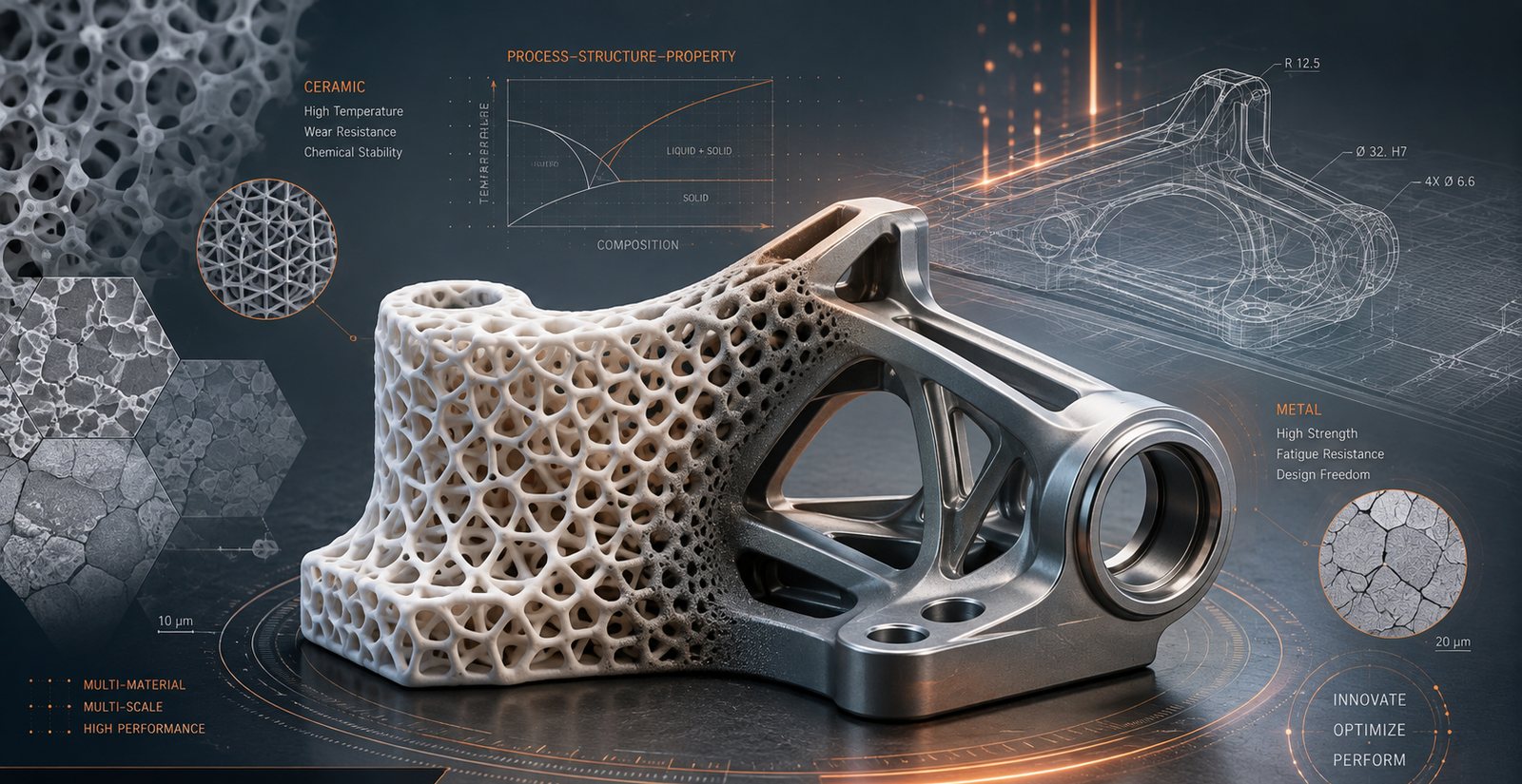
Process–structure–property relationship, tolerances, shrinkage and heat treatment: the numbers before the machine. Simulating means knowing in advance what would otherwise show up on the third batch.
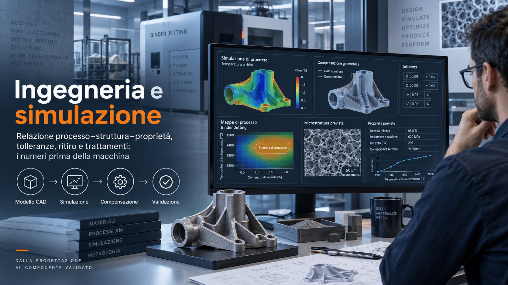
Process simulation answers four questions before the part exists: how much it shrinks, where it distorts, which dimensions will fall outside tolerance and whether it carries the load with the properties it will actually have after treatment.
The thread holding it together is the process–structure–property relationship: parameters set the microstructure, the microstructure sets the properties of the finished part. That is why designing with handbook values leads you astray.
In processes that go through sintering — metal binder jetting, MIM, technical ceramics — shrinkage is in the order of 15–20% linear and is not equal in the three directions. The geometry has to be compensated before printing: that is what makes the part conform, not machine calibration.
Bonora Technologies handles the engineering side: model setup, interpretation of results, compensation, first article measurement plan and iterative correction until conformity.
Three links in a single chain. You design the third, but you only control the first.
Printing parameters, green part density, sintering curve, furnace atmosphere, heat treatment. They are the only variables you act on directly, and they act on everything else.
Grain size and orientation, residual porosity, phases present, defects. It does not appear on a drawing and no caliper measures it: it shows in metallography, and it determines how the part will fail.
Density, strength, hardness, ductility, conductivity, dimensional stability. They are the consequence of the first two, not a starting figure: changing the furnace changes the number you write on the drawing.
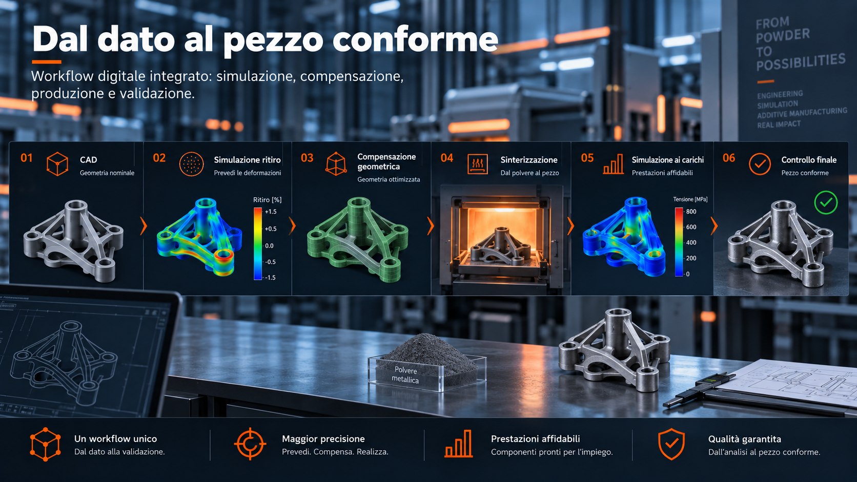
Six steps, in this order. Skipping one means finding the problem when it costs most.
The geometry at the dimensions the drawing calls for, the one the customer wants to receive. It is the target, not the file that goes to the machine — confusing the two is what produces an out-of-tolerance first batch.
The model predicts how densification contracts the part and where it distorts it, accounting for geometry, setters and gravity during the furnace cycle.
The geometry is deformed in the opposite direction, so that shrinkage brings it back to nominal. This, not the original CAD, is the file that gets printed.
Green part printing, debinding and the defined sintering cycle. From here the part follows physics: whatever was not predicted can no longer be corrected.
Structural verification with the actual properties of the sintered and treated material, not with wrought values. That is the difference between a calculation and a useful calculation.
First article scanning and measurement, comparison against nominal, correction of the compensation model. The model becomes reliable here, not before.
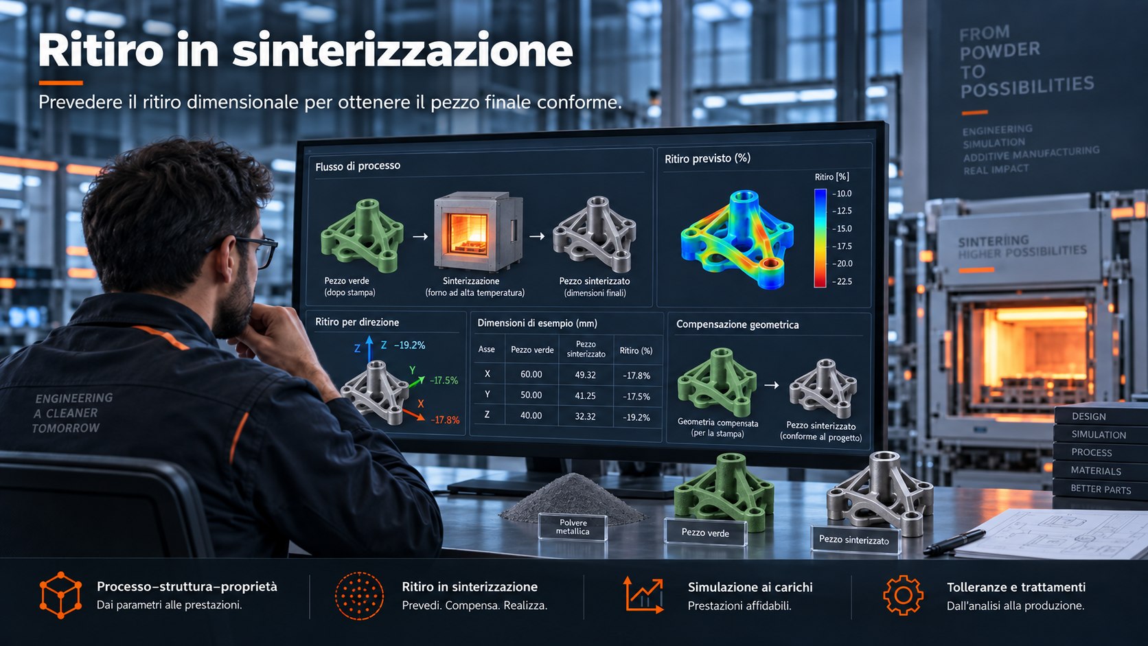
The phenomenon that decides whether the part comes out to size. Predicting it is the most useful part of the whole simulation.
The green part is a structure of particles held by a binder, with density far below the solid material. In the furnace the binder leaves and the particles bond: the volume the voids occupied disappears, and the part contracts.
Gravity, friction on the setters, density differences in the green body and print orientation make the three directions shrink by different amounts. That is why a single scale factor is almost never enough.
Thermal curve and peak temperature, green density, powder particle size, binder content, sintering setter geometry. Change one and the result moves, which is why they are frozen together with the printing parameters.
With specimens of known dimensions, built and sintered under the same conditions as the part and measured afterwards. A model not calibrated on the real furnace gives a credible, wrong number.
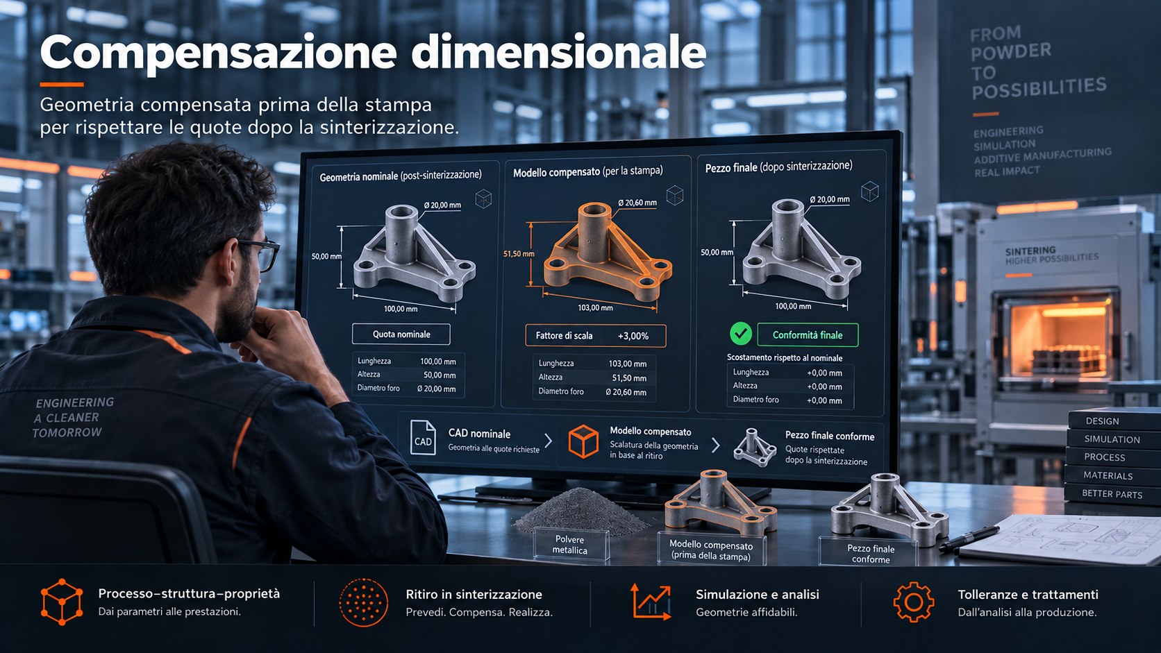
The file that goes to the machine is not the customer's drawing: it is the drawing deformed so the furnace brings it back to size.
The first approximation: everything is enlarged by the expected shrinkage percentage. It works on compact, simple shapes and is enough to start — but on an articulated geometry it leaves exactly the critical dimensions out of tolerance.
Three different factors on X, Y and Z, derived from specimens. This step solves most industrial cases and is also the cheapest to implement.
Not a scale but a point-by-point deformation derived from simulation: needed where the part has very different sections, overhangs or areas resting asymmetrically.
First article built, scanned and compared against nominal; the residual deviation feeds back into the compensation model. Two or three rounds almost always bring it inside tolerance.
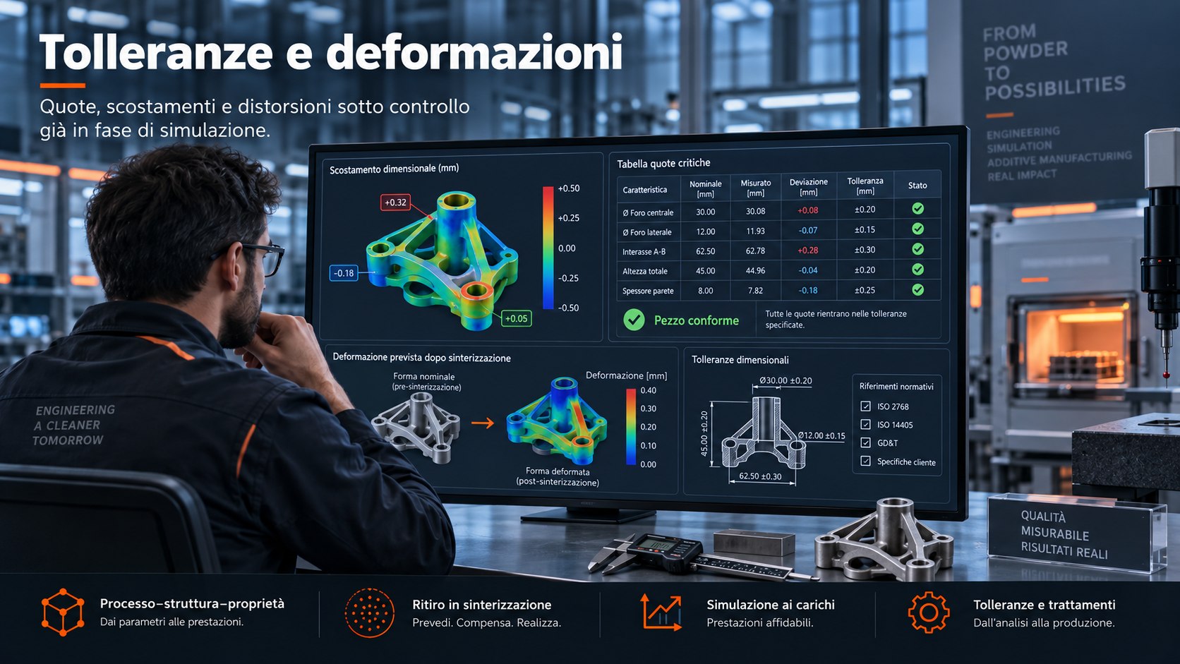
Which dimensions you can ask of the process and which you must ask of the machine tool. Deciding on the drawing costs nothing, deciding later costs the batch.
Shrinkage is predictable and compensated by scaling. Distortion is what remains afterwards: the part of the movement that depends on shape, setters and thermal gradients, which scaling cannot correct.
A well-set project distinguishes the dimensions the process can hold from those that must be ground or milled afterwards. Fits, bearing seats, sealing faces and datum surfaces almost always fall in the second group.
Measurement references must sit on surfaces that exist and are accessible after sintering, and must match those used in machining. A datum on a surface that will be machined away is a problem discovered in the metrology room.
General tolerances to ISO 2768, dimensional specification to ISO 14405 and geometric tolerancing to ISO 1101 (GD&T), plus any customer specification. The customer specification always outranks the general standard.
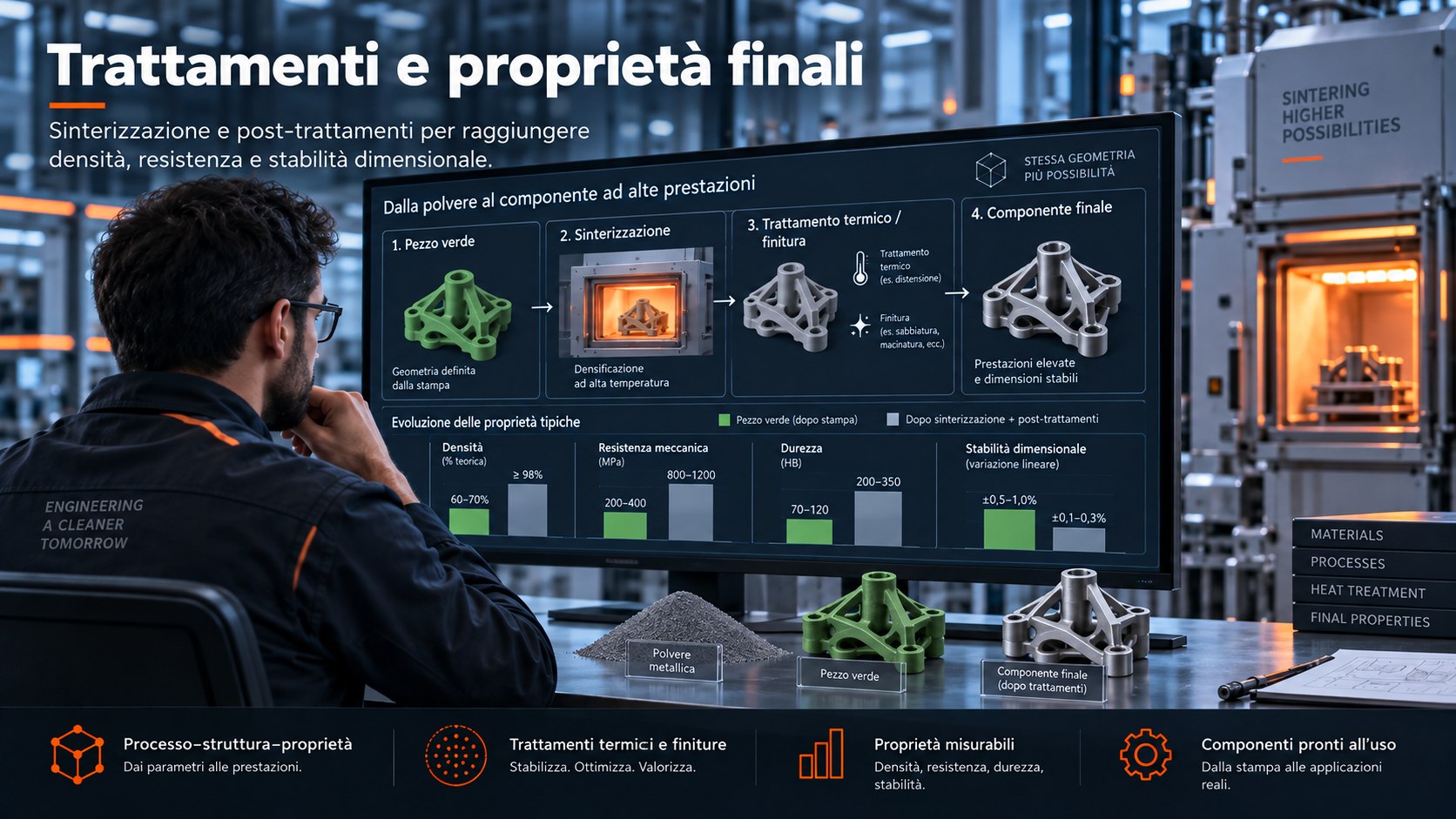
The part that leaves the printer is not the part you deliver. Between the two lie the steps that create the performance.
Thermal or chemical removal of the binder. It is the phase where the part is most fragile and where cracks and distortion appear that sintering then fixes permanently.
High-temperature densification in controlled atmosphere. The part moves from a structure of bonded particles to a continuous material, contracting by the 15–20% that compensation anticipated.
Hot isostatic pressing: it closes residual closed porosity and raises strength and fatigue life. On critical components it is not an option but a specification requirement.
Stress relief, solution annealing, ageing or quenching depending on the alloy. This is where the material reaches its declared properties: before treatment, it does not have the drawing values.
Blasting, tumbling, polishing, grinding of functional surfaces. It affects roughness, fatigue life and — on small parts — dimensions too.
Density, hardness and tensile testing on specimens sintered together with the part. It is the only proof that the process–structure–property chain worked on that batch.
| Property | Green part | After sintering and treatment |
|---|---|---|
| Density (% theoretical) | 60–70% | ≥ 98% |
| Mechanical strength | 200–400 MPa | 800–1,200 MPa |
| Hardness | 70–120 HB | 200–350 HB |
| Dimensional stability | ±0.5–1.0% | ±0.1–0.3% |
The figures are an example on sintered steel, given to show the order of magnitude of the jump between green and finished part. They are not a specification: they depend on the alloy, the sintering curve and the treatment, and must be verified on batch specimens.
A structural check is worth exactly as much as the material data you feed it. A sintered or layer-built part does not have wrought properties: it carries residual porosity, often behaves differently along the build axis, and has a surface that weighs more on fatigue than it does in a static calculation.
The correct approach is to feed the calculation with values measured on process specimens — not with the powder supplier's datasheet — and to treat anisotropy as a material property rather than as extra safety margin. Where data is missing, the safety factor covers ignorance, and it should be declared as such.
The useful result is not the coloured map: it is the answer to three questions. Does the part hold? Where does it fail first? And can that area be measured or inspected in production?
Native CAD or STEP of the nominal geometry, at the dimensions you want to receive. A dimensioned 2D drawing as well is better still: it says which dimensions genuinely matter.
Loads, constraints, service temperature, environment, expected cycles. Without the load case a structural simulation cannot be set up, and without real conditions you simulate the wrong part.
If they are already decided, we start there. If not, we choose them together: this is the best moment, because downstream every change costs a requalification.
Which tolerances are genuinely binding and how many parts per year. The first decide what gets machined afterwards, the second decide whether the project makes economic sense.
The order of magnitude is 15–20% linear, but the exact figure cannot be given in advance: it depends on the alloy, green density, sintering curve and part geometry, and it differs between the three directions. The useful value comes from building specimens of known dimensions under the same conditions as the part and measuring them after the furnace. Anyone quoting a percentage over the phone, without seeing the part, is guessing.
On a compact, simple shape often yes, and it is the correct starting point. On geometries with very different sections, overhangs or asymmetric supports, no: the part does not merely shrink, it distorts. There you need directional compensation or, in the hardest cases, a deformation field derived from simulation.
They depend on the process, part size and the area considered, and they are not comparable with milling. The practical rule is to design by separating the dimensions the process can hold from those that must be machined afterwards: fits, bearing seats and sealing faces almost always fall in the second group and need machining stock planned from the start.
No, and anyone promising that is selling. Simulation reduces the number of iterations — often from five or six to two — and above all tells you where to look when you measure. The first article remains the only proof that the model is calibrated to your furnace and your powder.
Those measured on specimens built and treated like the part, not those on the wrought material datasheet. On an additive component the difference can be substantial, particularly on ductility and fatigue life, and it must be held together with anisotropy relative to the build axis.
Yes, but it answers different questions. In laser powder bed fusion there is no sintering shrinkage: there are residual stresses generated by thermal gradients, which distort the part when it is cut from the plate and can crack it during the build. There, simulation serves to choose orientation and supports and to predict distortion after cutting.
Send us the 3D model and the operating conditions: we simulate shrinkage, distortion and load behaviour, and tell you which dimensions hold and which need machining.
Let us look at your component →